In this issue, we will describe model-based development and actual application examples, which have become commonplace in automotive control development.
What is Model-Based Development?
First, as we understand model-based development, we consider it in a broad sense to be modeling the development target and building a control or system based on that model. It refers to modeling the development target at the granularity of the model according to the development objectives and phases, and then conceptualizing, designing, and examining the model accordingly.
Therefore, for example, when building controls, etc. using models expressed in languages such as Excel or Python, it can be said that these are also model-based development. On the other hand, when models are built using such languages, it is difficult to understand the models visually, and it takes a lot of man-hours to implement the code in the ECU. Therefore, MATLAB Simulink by MathWorks is generally used in the development field.

In this figure, addition and transfer function blocks appear. simulink can connect these blocks with lines to describe processes such as quadrature operations, differential and integral calculus, wasted time, and previous value, and to construct a model. In addition, the model constructed here can be converted to C language by auto code using Mathworks products such as simulink Coder, and this converted C language can be implemented on a microcontroller. In practical use, there exists know-how for creating models for smooth implementation on a microcontroller, such as setting appropriate types of variables when creating models according to the specifications of the microcontroller and using discretization blocks to describe the entire model.
Characteristics of Model-Based Development
In general, model-based development has the following characteristics, advantages and disadvantages
(This information is taken from the Toshiba Information Systems website.)
feature
1. Models become working specifications
2. Automatic code generation can be done
3. Improved accuracy and reduced time for calibration and evaluation
Advantages
1. Quality improvement of specifications
2. Quality improvement during software creation
3. Quality improvement during verification (inclusion of defects)
4. Visualization and management of changes
5. Ability to reuse models
demerit
1. Temporary increase in design man-hours in the initial stage of introduction
2. Need for education and human resource development
3. Need to rebalance the development system at the time of introduction
Basically, by using models from the early development stage, it is possible to pass the work between phases using models, which is beneficial in reducing rework and shortening verification time.
For example, the figure below shows an example of the software development process. The design phase, circled in blue, also involves simulation using models, which increases the man-hours required for the design phase. On the other hand, during the verification phase, the number of parts that can be verified by simulation increases, and if the modeling is done at a granular level appropriate for the phase, the ratio of NG in the actual machine verification will decrease, thus reducing the man-hours spent in the verification phase.
Therefore, although in many cases it leads to a reduction in overall man-hours, the change in the way work is done results in an increase in man-hours for the design process and a decrease in man-hours for the verification process, which may require reallocation of personnel when introducing new model-based development.

The following is a graph of the change in man-hours before and after the introduction of model-based development, created by Toshiba Information Systems.

System modeling
In model-based development, it is necessary to model the control object. Here, we will describe the equations of motion in simulink as a simple modeling.
Let us consider the case where an object of mass M is subjected to an external force F, a resistive force R, and a velocity-proportional resistance C. When describing this in simulink, we will model it by integrating the acceleration.

The modeling is shown below. Here the parameters of the model are mass M = 10 [kg], external force F = 12 [N], resistance R = 2 [N], and velocity proportional resistance C = 5 [N/(m/s)].
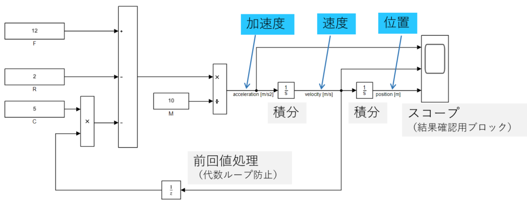
Let’s simulate the above model. Hand calculation shows that at velocity 0 m/s, the acceleration is (12-2)[N]/10 [kg] = 1 [m/s^2]and the equilibrium point of velocity is (12-2)[N]/5 [N/(m/s)] = 2 [m/s].
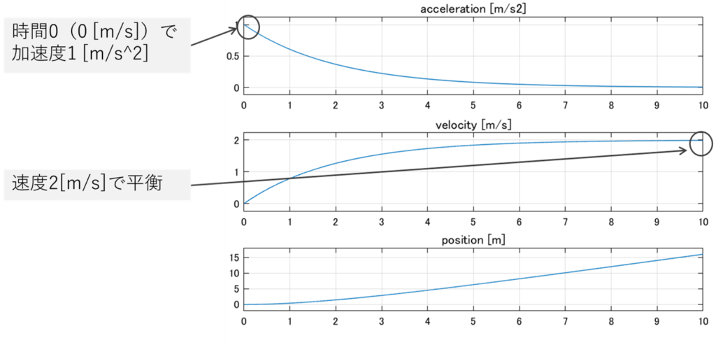
The model seems to be done correctly.
In reality, for example, it is rare for the damping coefficient to be a constant value with respect to speed. In addition, when hydraulic dampers are used, the viscosity coefficient of oil changes with temperature, resulting in a change in damping coefficient. It is also common to have different damping coefficients on the extension and contraction sides, so it is necessary to include such characteristics. In the following example, LookUpTable is used to express the state in which the damping coefficient changes with speed.

In this way, we start the verification with the simplest model and gradually describe the object to be modeled in detail. For example, in the case of in-house production of a fuel economy simulator for a hybrid vehicle, we model components such as the engine, battery, motor, generator, etc. on our own.
Equipment used in the design and verification of model-based development in vehicles
The following diagram is commonly used in the design and verification process of model-based development.

The leftmost one is called MILS or SILS, and it is mainly used to design and verify the operation of a control controller against a plant model that models a control target in a computer (PC). If the controller in MILS is designed in such a way that it can be directly implemented in an ECU, it is rare for the calculation results in MILS to differ from those in SILS.
The second from the left is called HILS, which connects a real controller to a simulator that simulates a vehicle to verify the real controller. SCALEXIO from dSPACE is often used for this simulator. The major advantages of using a real controller are that the microcontroller resource usage can be verified and the behavior of the real controller when physical or software failures occur can be observed because the vehicle is simulated by the simulator.
The two benches on the right and the chassis dynamometer are used for development even without model-based development. The use of the bench in model-based development is not only to check the operation of the actual machine, but also to improve the accuracy of the model by feeding back the behavior of the actual parts assembled on the bench to the model corresponding to the actual machine used in model-based development, thereby improving the accuracy of the design in the previous process. This is the point that the accuracy of the model can be improved by feeding back the actual part behavior to the model used in model-based development. If the bench results differ from the model results, the model is modified and the design is redesigned. The same is true for the chassis dynamometer. By incorporating experimental data from the actual vehicle into the model, the simulator accuracy of the model can be improved and the efficiency of the design process can be increased, in addition to confirming that the movement of the actual vehicle is as simulated so far.
There is also a pattern called Rapid Control Prototyping (RCP), which uses a general-purpose controller and a real control object. For example, a dSPACE Micro Auto Box is used in combination with an actual vehicle for verification. This method is used to quickly conduct vehicle tests with a new system, for example, by reducing the amount of time required to implement the system on the actual controller.
Automotive Development Process
Before proceeding to an example of the application of model-based development, we will discuss the process of automobile development. If the higher level concepts in automotive development are not properly communicated downstream, the design requirements and verification contents of the verification process will deviate from the original intent when they are incorporated into model-based development.
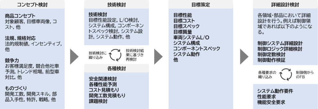
The figure above shows an example of the automobile development process. First, a vehicle concept is determined from the viewpoints of product concept, compliance with regulations and standards, competitiveness, and manufacturing in the concept study phase. Then, technical studies are conducted to determine if the concept is feasible. At this time, safety-related considerations, performance, cost, and other various considerations are incorporated into the technical study. Then, based on the technical study, we formulate each goal for the product. Finally, detailed design studies are conducted to achieve the established goals. In this diagram, the control-related items are described, and while incorporating each requirement and demand, detailed design study is conducted from the control system configuration to the logic creation stage.
Example of application of model-based development to automotive development
I will now explain an example of application to automobile development, which is the main topic. Here, we will use the development of a controller for a hybrid vehicle as an example.
The following figure roughly illustrates the development flow from the establishment of fuel efficiency targets to the implementation of the hybrid controller.
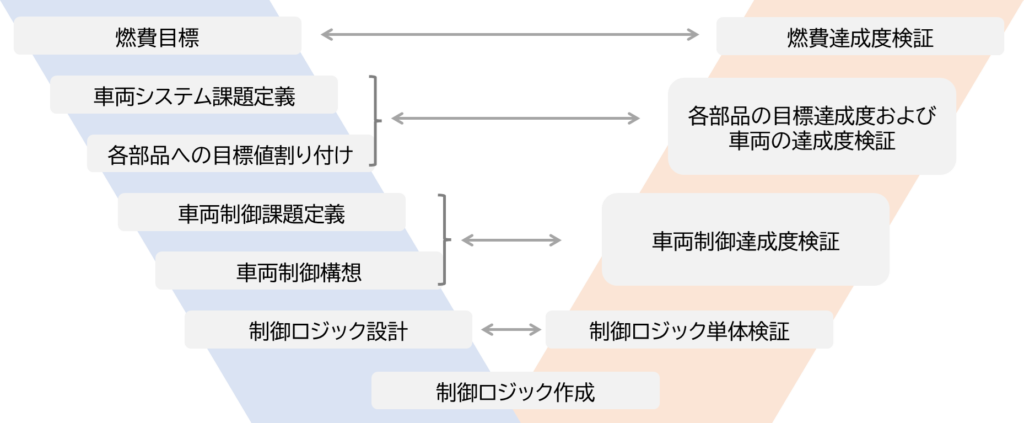
The left side of this diagram shows the design process and the right side shows the verification process. In the phases corresponding to the left and right sides, design and verification are paired to confirm that the actual design is properly done. The following is an explanation starting from the top.
The first step is to establish fuel efficiency targets, which are often determined based on the regulations of each country, incentives, competitiveness against competitors’ vehicles, and other factors. The next step is to define the vehicle system issues and assign target values to each component. The assignment of target values to each component is determined by determining where a realistic solution is likely to be found. If the initial target for fuel efficiency is strict, then the requirements for each component will naturally be strict as well. If there is an error in the estimation of the effect allowance here, it will have a large impact on the subsequent processes, so simulations are carefully conducted to calculate the allowance.
Next, in the definition of vehicle control issues and vehicle control concept, we consider what kind of control logic is needed to achieve the way each component moves, which was done in the fuel efficiency study in the previous process, and formulate a concept. We then design and create the control logic based on this concept. As we accumulate knowledge of model-based development within the company, we are able to use accurate vehicle and controller models from the vehicle system problem definition phase of the previous process, and we are able to design control logic based on those models, making these processes more efficient. Of course, it is normal for the vehicle to be adapted to different vehicles, so the models of each component, etc. must be reworked, and as the development of each component progresses, the models of each component must be reworked, and the controller must be re-designed and simulated repeatedly.
Next, logic is created in AutoCode and the control logic is verified on a stand-alone basis. Here, we mainly use MILS and SILS to check whether the logic behaves as expected and whether there is any abnormal behavior when inputs in the range not normally expected are received. We define the necessary input conditions from the logic configuration, and repeat simulations on a PC to guarantee the operation of each control logic alone.
After that, the logic is connected together to verify the behavior of the controller as a whole. Since MILS/SILS tends to take less time per simulation than HILS, we separate the items to be checked in MILS/SILS from those in HILS and reduce the number of items to be checked in HILS relative to those in MILS/SILS to make development as efficient as possible. Therefore, we will separate the items to be checked in MILS/SILS from those to be checked in HILS, and reduce the number of items to be checked in HILS relative to those to be checked in MILS/SILS to make development as efficient as possible.
Next, after conducting stand-alone verification of each component on the bench, we evaluate the degree of achievement at the vehicle level by running the actual vehicle on the chassis dynamometer and test course. As a result of being assembled into a vehicle, errors in the variability of each component accumulate, and the behavior of each component after being assembled into a system may differ slightly from what has been assumed on the bench. In the development of fuel efficiency performance, the results of experiments on the chassis dynamometer are compared with the results of experiments on the simulator, the simulator side is corrected, and the control controller is fine-tuned. In particular, transient movements such as engine torque output and fuel consumption often differ from the results on the bench, so adjustments are made based on the results on the actual vehicle.
The final evaluation of fuel economy achievement is ultimately assessed by a fuel economy certification test. The certification test is the final challenge.
postscript
In this technical column, I have written an article on the application of model-based development to automotive development. We believe that model-based development reduces rework during development and improves design quality. Model-based development is already popular in the automotive industry, but even if it is called model-based development, the method and scale differ depending on what the target of development is and where it is applied in the development phase. We believe that model-based development will spread beyond the automotive industry, starting with those areas where it can be introduced on a small scale.
Blue Sky Technology is a unique consulting and engineering services firm specializing in automotive electrification and related technologies, with a majority of its staff having worked in the automotive industry for 20 to 30 years.
From specialized requests such as development and design of electric vehicles, dynamic evaluation of vehicles, overhaul investigations, vehicle control, motor control, R&D of lithium-ion batteries and start-up of production lines, to consulting on electrification of each automotive component and adaptation of new materials to electric vehicles, We can provide support tailored to your needs.

